Magnetic Induction Applications
Induced EMF and Magnetic Flux
Faraday’s law of induction states that an electromotive force is induced by a change in the magnetic flux.
Learning Objectives
Explain the relationship between the magnetic field and the electromotive force
Key Takeaways
Key Points
- It is a change in the magnetic field flux that results in an electromotive force (or voltage).
- The magnetic flux (often denoted Φ or ΦB) through a surface is the component of the magnetic field passing through that surface.
- In the most general form, magnetic flux is defined as [latex]\Phi_{\text{B}} = \iint_{\text{A}} \mathbf{\text{B}} \cdot \text{d}\mathbf {\text{A}}[/latex]. It is the integral (sum) of all of the magnetic field passing through infinitesimal area elements dA.
Key Terms
- vector area: A vector whose magnitude is the area under consideration, and whose direction is perpendicular to the surface area.
- galvanometer: An analog measuring device, denoted by G, that measures current flow using a needle deflection caused by a magnetic field force acting upon a current-carrying wire.
Induced EMF
The apparatus used by Faraday to demonstrate that magnetic fields can create currents is illustrated in the following figure. When the switch is closed, a magnetic field is produced in the coil on the top part of the iron ring and transmitted (or guided) to the coil on the bottom part of the ring. The galvanometer is used to detect any current induced in a separate coil on the bottom.
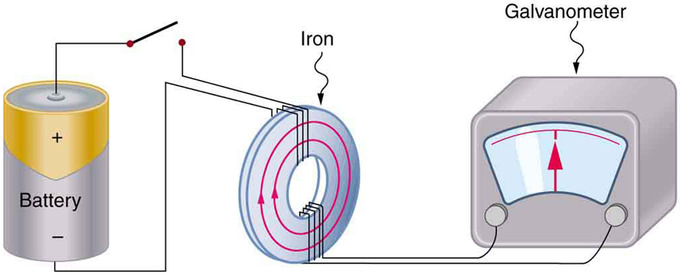
Faraday’s Apparatus: This is Faraday’s apparatus for demonstrating that a magnetic field can produce a current. A change in the field produced by the top coil induces an EMF and, hence, a current in the bottom coil. When the switch is opened and closed, the galvanometer registers currents in opposite directions. No current flows through the galvanometer when the switch remains closed or open.
It was found that each time the switch is closed, the galvanometer detects a current in one direction in the coil on the bottom. Each time the switch is opened, the galvanometer detects a current in the opposite direction. Interestingly, if the switch remains closed or open for any length of time, there is no current through the galvanometer. Closing and opening the switch induces the current. It is the change in magnetic field that creates the current. More basic than the current that flows is the electromotive force (EMF) that causes it. The current is a result of an EMF induced by a changing magnetic field, whether or not there is a path for current to flow.
Magnetic Flux
The magnetic flux (often denoted Φ or ΦB) through a surface is the component of the magnetic field passing through that surface. The magnetic flux through some surface is proportional to the number of field lines passing through that surface. The magnetic flux passing through a surface of vector area A is
[latex]\Phi_\text{B} = \mathbf{\text{B}} \cdot \mathbf{\text{A}} = \text{BA} \cos \theta[/latex],
where B is the magnitude of the magnetic field (having the unit of Tesla, T), A is the area of the surface, and θ is the angle between the magnetic field lines and the normal (perpendicular) to A.
For a varying magnetic field, we first consider the magnetic flux [latex]\text{d}\Phi _\text{B}[/latex] through an infinitesimal area element dA, where we may consider the field to be constant:
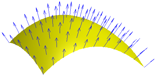
Varying Magnetic Field: Each point on a surface is associated with a direction, called the surface normal; the magnetic flux through a point is then the component of the magnetic field along this normal direction.
[latex]\text{d}\Phi_\text{B} = \mathbf{\text{B}} \cdot \text{d}\mathbf{\text{A}}[/latex]
A generic surface, A, can then be broken into infinitesimal elements and the total magnetic flux through the surface is then the surface integral
[latex]\Phi_\text{B} = \iint_\text{A} \mathbf{\text{B}} \cdot \text{d}\mathbf {\text{A}}[/latex].
Faraday’s Law of Induction and Lenz’ Law
Faraday’s law of induction states that the EMF induced by a change in magnetic flux is [latex]\text{EMF} = -\text{N}\frac{\Delta \Phi}{\Delta \text{t}}[/latex], when flux changes by Δ in a time Δt.
Learning Objectives
Express the Faraday’s law of induction in a form of equation
Key Takeaways
Key Points
- The minus in the Faraday’s law means that the EMF creates a current I and magnetic field B that oppose the change in flux Δthis is known as Lenz’ law.
- Faraday’s law of induction is the fundamental operating principle of transformers, inductors, and many types of electrical motors, generators, and solenoids.
- Faraday’s law states that the EMF induced by a change in magnetic flux depends on the change in flux Δ, time Δt, and number of turns of coils.
Key Terms
- electromotive force: (EMF)—The voltage generated by a battery or by the magnetic force according to Faraday’s Law. It is measured in units of volts, not newtons, and thus, is not actually a force.
- solenoid: A coil of wire that acts as a magnet when an electric current flows through it.
- flux: The rate of transfer of energy (or another physical quantity) through a given surface, specifically electric flux or magnetic flux.
Faraday’s Law of Induction
Faraday’s law of induction is a basic law of electromagnetism that predicts how a magnetic field will interact with an electric circuit to produce an electromotive force (EMF). It is the fundamental operating principle of transformers, inductors, and many types of electrical motors, generators, and solenoids.
Faraday’s experiments showed that the EMF induced by a change in magnetic flux depends on only a few factors. First, EMF is directly proportional to the change in flux Δ. Second, EMF is greatest when the change in time Δt is smallest—that is, EMF is inversely proportional to Δt. Finally, if a coil has N turns, an EMF will be produced that is N times greater than for a single coil, so that EMF is directly proportional to N. The equation for the EMF induced by a change in magnetic flux is
[latex]\text{EMF} = -\text{N}\frac{\Delta \Phi}{\Delta \text{t}}[/latex].
This relationship is known as Faraday’s law of induction. The units for EMF are volts, as is usual.
Lenz’ Law
The minus sign in Faraday’s law of induction is very important. The minus means that the EMF creates a current I and magnetic field B that oppose the change in flux Δthis is known as Lenz’ law. The direction (given by the minus sign) of the EMF is so important that it is called Lenz’ law after the Russian Heinrich Lenz (1804–1865), who, like Faraday and Henry, independently investigated aspects of induction. Faraday was aware of the direction, but Lenz stated it, so he is credited for its discovery.
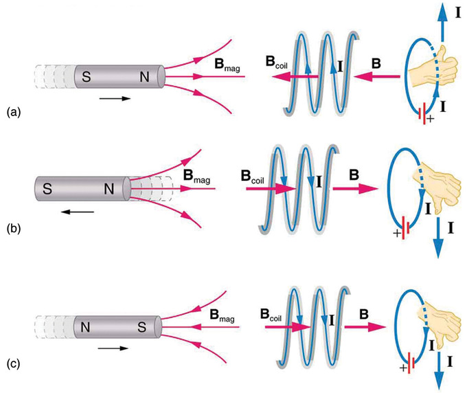
Lenz’ Law: (a) When this bar magnet is thrust into the coil, the strength of the magnetic field increases in the coil. The current induced in the coil creates another field, in the opposite direction of the bar magnet’s to oppose the increase. This is one aspect of Lenz’s law—induction opposes any change in flux. (b) and (c) are two other situations. Verify for yourself that the direction of the induced Bcoil shown indeed opposes the change in flux and that the current direction shown is consistent with the right hand rule.
Energy Conservation
Lenz’ law is a manifestation of the conservation of energy. The induced EMF produces a current that opposes the change in flux, because a change in flux means a change in energy. Energy can enter or leave, but not instantaneously. Lenz’ law is a consequence. As the change begins, the law says induction opposes and, thus, slows the change. In fact, if the induced EMF were in the same direction as the change in flux, there would be a positive feedback that would give us free energy from no apparent source—conservation of energy would be violated.
Motional EMF
Motion in a magnetic field that is stationary relative to the Earth induces motional EMF (electromotive force).
Learning Objectives
Identify process that induces motional electromotive force
Key Takeaways
Key Points
- Faraday’s law of induction can be used to calculate the motional EMF when a change in magnetic flux is caused by a moving element in a system.
- That a moving magnetic field produces an electric field (and conversely that a moving electric field produces a magnetic field) is part of the reason electric and magnetic forces are now considered as different manifestations of the same force.
- Any change in magnetic flux induces an electromotive force (EMF) opposing that change—a process known as induction. Motion is one of the major causes of induction.
Key Terms
- electromotive force: (EMF)—The voltage generated by a battery or by the magnetic force according to Faraday’s Law. It is measured in units of volts, not newtons, and thus, is not actually a force.
- magnetic flux: A measure of the strength of a magnetic field in a given area.
- induction: The generation of an electric current by a varying magnetic field.
As seen in previous Atoms, any change in magnetic flux induces an electromotive force (EMF) opposing that change—a process known as induction. Motion is one of the major causes of induction. For example, a magnet moved toward a coil induces an EMF, and a coil moved toward a magnet produces a similar EMF. In this Atom, we concentrate on motion in a magnetic field that is stationary relative to the Earth, producing what is loosely called motional EMF.
Motional EMF
Consider the situation shown in. A rod is moved at a speed v along a pair of conducting rails separated by a distance ℓ in a uniform magnetic field B. The rails are stationary relative to B, and are connected to a stationary resistor R (the resistor could be anything from a light bulb to a voltmeter). Consider the area enclosed by the moving rod, rails and resistor. B is perpendicular to this area, and the area is increasing as the rod moves. Thus the magnetic flux enclosed by the rails, rod and resistor is increasing. When flux changes, an EMF is induced according to Faraday’s law of induction.
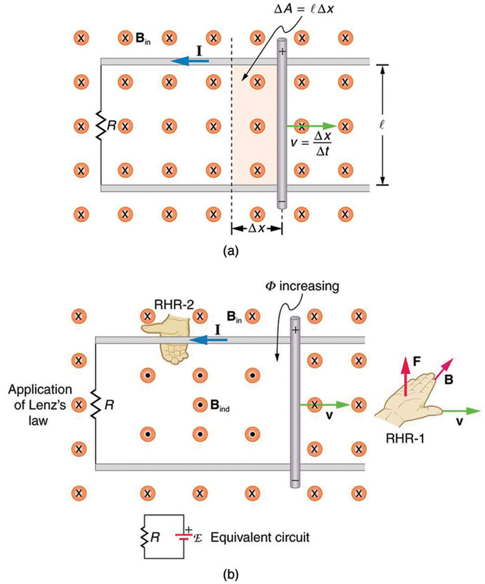
Motional EMF: (a) A motional emf=Bℓv is induced between the rails when this rod moves to the right in the uniform magnetic field. The magnetic field B is into the page, perpendicular to the moving rod and rails and, hence, to the area enclosed by them. (b) Lenz’s law gives the directions of the induced field and current, and the polarity of the induced emf. Since the flux is increasing, the induced field is in the opposite direction, or out of the page. Right hand rule gives the current direction shown, and the polarity of the rod will drive such a current.
To find the magnitude of EMF induced along the moving rod, we use Faraday’s law of induction without the sign:
[latex]\text{EMF} = \text{N}\frac{\Delta \Phi}{\Delta \text{t}}[/latex].
In this equation, N=1 and the flux Φ=BAcosθ. We have θ=0º and cosθ=1, since B is perpendicular to A. Now Δ=Δ(BA)=BΔA, since B is uniform. Note that the area swept out by the rod is ΔA=ℓx. Entering these quantities into the expression for EMF yields:
[latex]\text{EMF} = \frac{\text{B}\Delta \text{A}}{\Delta \text{t}} = \text{B} \frac{\text{l} \Delta \text{x}}{\Delta \text{t}} = \text{Blv}[/latex].
To find the direction of the induced field, the direction of the current, and the polarity of the induced EMF we apply Lenz’ law, as explained in Faraday’s Law of Induction: Lenz’ Law. As seen in Fig 1 (b), F lux is increasing, since the area enclosed is increasing. Thus the induced field must oppose the existing one and be out of the page. (The right hand rule requires that I be counterclockwise, which in turn means the top of the rod is positive, as shown. )
Electric Field vs. Magnetic Field
There are many connections between the electric force and the magnetic force. That a moving magnetic field produces an electric field (and conversely that a moving electric field produces a magnetic field) is part of the reason electric and magnetic forces are now considered as different manifestations of the same force (first noticed by Albert Einstein). This classic unification of electric and magnetic forces into what is called the electromagnetic force is the inspiration for contemporary efforts to unify other basic forces.
Back EMF, Eddy Currents, and Magnetic Damping
Back EMF, eddy currents, and magnetic damping are all due to induced EMF and can be explained by Faraday’s law of induction.
Learning Objectives
Explain the relationship between the motional electromotive force, eddy currents, and magnetic damping
Key Takeaways
Key Points
- Input EMF that powers a motor can be opposed by the motor’s self-generated EMF, called the back EMF of the motor.
- If motional EMF can cause a current loop in the conductor, the current is called an eddy current.
- Eddy currents can produce significant drag, called magnetic damping, on the motion involved.
Key Terms
- electromotive force: (EMF)—The voltage generated by a battery or by the magnetic force according to Faraday’s Law. It is measured in units of volts, not newtons, and thus, is not actually a force.
- Faraday’s law of induction: A basic law of electromagnetism that predicts how a magnetic field will interact with an electric circuit to produce an electromotive force (EMF).
Back EMF
Motors and generators are very similar. (Read our Atoms on “Electric Generators” and “Electric Motors. “) Generators convert mechanical energy into electrical energy, whereas motors convert electrical energy into mechanical energy. Furthermore, motors and generators have the same construction. When the coil of a motor is turned, magnetic flux changes, and an electromotive force (EMF), consistent with Faraday’s law of induction, is induced. The motor thus acts as a generator whenever its coil rotates. This will happen whether the shaft is turned by an external input, like a belt drive, or by the action of the motor itself. That is, when a motor is doing work and its shaft is turning, an EMF is generated. Lenz’ law tells us the induced EMF opposes any change, so that the input EMF that powers the motor will be opposed by the motor’s self-generated EMF, called the back EMF of the motor.
Eddy Current
As discussed in “Motional EMF,” motional EMF is induced when a conductor moves in a magnetic field or when a magnetic field moves relative to a conductor. If motional EMF can cause a current loop in the conductor, we refer to that current as an eddy current. Eddy currents can produce significant drag, called magnetic damping, on the motion involved.
Consider the apparatus shown in, which swings a pendulum bob between the poles of a strong magnet. If the bob is metal, there is significant drag on the bob as it enters and leaves the field, quickly damping the motion. If, however, the bob is a slotted metal plate, as shown in (b), there is a much smaller effect due to the magnet. There is no discernible effect on a bob made of an insulator.
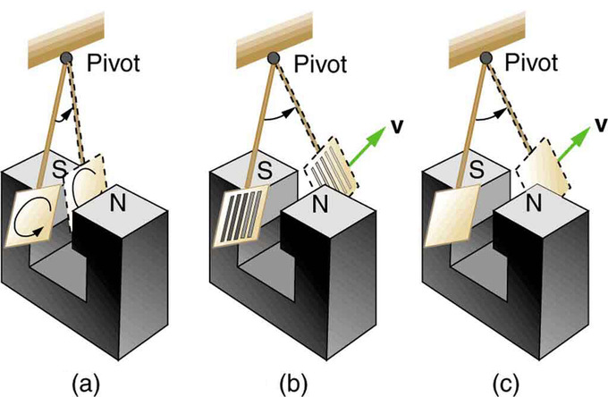
Device for Exploring Eddy Currents and Magnetic Damping: A common physics demonstration device for exploring eddy currents and magnetic damping. (a) The motion of a metal pendulum bob swinging between the poles of a magnet is quickly damped by the action of eddy currents. (b) There is little effect on the motion of a slotted metal bob, implying that eddy currents are made less effective. (c) There is also no magnetic damping on a nonconducting bob, since the eddy currents are extremely small.
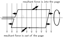
shows what happens to the metal plate as it enters and leaves the magnetic field. In both cases, it experiences a force opposing its motion. As it enters from the left, flux increases, and so an eddy current is set up (Faraday’s law) in the counterclockwise direction (Lenz’ law), as shown. Only the right-hand side of the current loop is in the field, so that there is an unopposed force on it to the left (right hand rule). When the metal plate is completely inside the field, there is no eddy current if the field is uniform, since the flux remains constant in this region. But when the plate leaves the field on the right, flux decreases, causing an eddy current in the clockwise direction that, again, experiences a force to the left, further slowing the motion. A similar analysis of what happens when the plate swings from the right toward the left shows that its motion is also damped when entering and leaving the field.
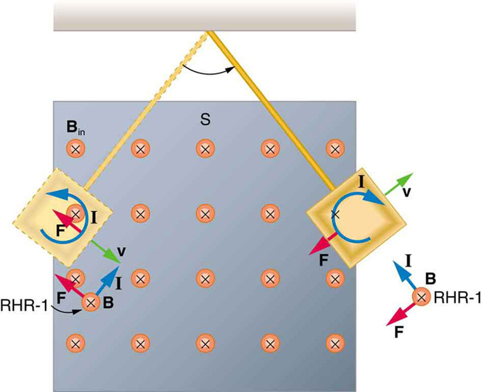
Conducting Plate Passing Between the Poles of a Magnet: A more detailed look at the conducting plate passing between the poles of a magnet. As it enters and leaves the field, the change in flux produces an eddy current. Magnetic force on the current loop opposes the motion. There is no current and no magnetic drag when the plate is completely inside the uniform field.
When a slotted metal plate enters the field, as shown in, an EMF is induced by the change in flux, but it is less effective because the slots limit the size of the current loops. Moreover, adjacent loops have currents in opposite directions, and their effects cancel. When an insulating material is used, the eddy current is extremely small, and so magnetic damping on insulators is negligible. If eddy currents are to be avoided in conductors, then they can be slotted or constructed of thin layers of conducting material separated by insulating sheets.
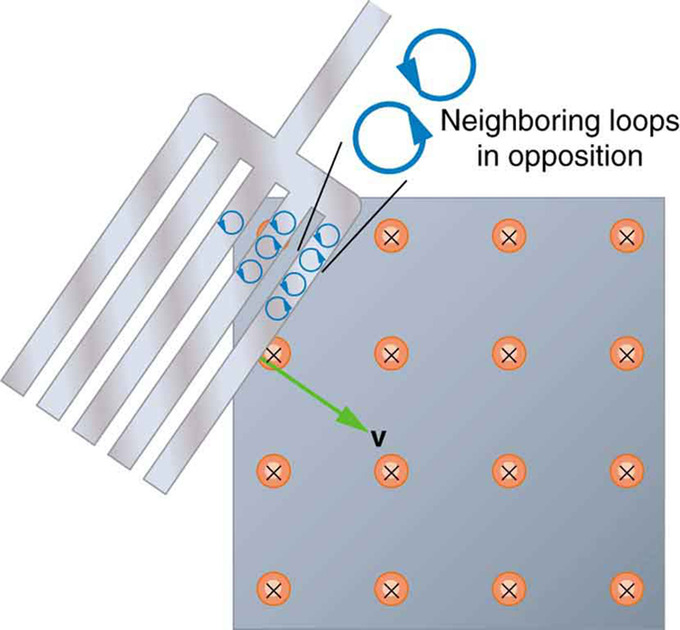
Eddy Currents Induced in a Slotted Metal Plate: Eddy currents induced in a slotted metal plate entering a magnetic field form small loops, and the forces on them tend to cancel, thereby making magnetic drag almost zero.
Changing Magnetic Flux Produces an Electric Field
Faraday’s law of induction states that changing magnetic field produces an electric field: [latex]\varepsilon = -\frac{\partial \Phi_\text{B}}{\partial \text{t}}[/latex].
Learning Objectives
Describe the relationship between the changing magnetic field and an electric field
Key Takeaways
Key Points
- Faraday’s law of induction is a basic law of electromagnetism that predicts how a magnetic field will interact with an electric circuit to produce an electromotive force.
- An alternative, differential form of Faraday’s law of induction is express in the equation [latex]\nabla \times \vec {\text{E}} = - \frac{\partial \vec {\text{B}}}{\partial \text{t}}[/latex].
- Faraday’s law of induction is one of the four equations in Maxwell’s equations, governing all electromagnetic phenomena.
Key Terms
- vector area: A vector whose magnitude is the area under consideration and whose direction is perpendicular to the plane.
- Maxwell’s equations: A set of equations describing how electric and magnetic fields are generated and altered by each other and by charges and currents.
- Stokes’ theorem: a statement about the integration of differential forms on manifolds, which both simplifies and generalizes several theorems from vector calculus.
We have studied Faraday’s law of induction in previous atoms. We learned the relationship between induced electromotive force (EMF) and magnetic flux. In a nutshell, the law states that changing magnetic field [latex](\frac{\text{d} \Phi_\text{B}}{\text{dt}})[/latex] produces an electric field [latex](\varepsilon)[/latex], Faraday’s law of induction is expressed as [latex]\varepsilon = -\frac{\partial \Phi_\text{B}}{\partial \text{t}}[/latex], where [latex]\varepsilon[/latex] is induced EMF and [latex]\Phi_\text{B}[/latex] is magnetic flux. (“N” is dropped from our previous expression. The number of turns of coil is included can be incorporated in the magnetic flux, so the factor is optional. ) Faraday’s law of induction is a basic law of electromagnetism that predicts how a magnetic field will interact with an electric circuit to produce an electromotive force (EMF). In this Atom, we will learn about an alternative mathematical expression of the law.
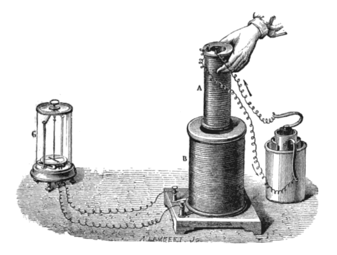
Faraday’s Experiment: Faraday’s experiment showing induction between coils of wire: The liquid battery (right) provides a current which flows through the small coil (A), creating a magnetic field. When the coils are stationary, no current is induced. But when the small coil is moved in or out of the large coil (B), the magnetic flux through the large coil changes, inducing a current which is detected by the galvanometer (G).
Differential form of Faraday’s law
The magnetic flux is [latex]\Phi_\text{B} = \int_\text{S} \vec {\text{B}} \cdot \text{d} \vec {\text{A}}[/latex], where [latex]\vec {\text{A}}[/latex] is a vector area over a closed surface S. A device that can maintain a potential difference, despite the flow of current is a source of electromotive force. (EMF) The definition is mathematically [latex]\varepsilon = \oint_\text{C} \vec {\text{E}} \cdot \text{d}\vec {\text{s}}[/latex], where the integral is evaluated over a closed loop C.
Faraday’s law now can be rewritten [latex]\oint_\text{C} \vec {\text{E}} \cdot \text{d}\vec {\text{s}} = -\frac{\partial}{\partial \text{t}} (\int \vec {\text{B}} \cdot \text{d}\vec {\text{A}})[/latex]. Using the Stokes’ theorem in vector calculus, the left hand side is[latex]\oint_\text{C} \vec {\text{E}} \cdot \text{d}\vec {\text{s}} = \int_\text{S} (\nabla \times \vec {\text{E}}) \cdot \text{d}\vec {\text{A}}[/latex]. Also, note that in the right hand side[latex]\frac{\partial}{\partial \text{t}} (\int \vec {\text{B}} \cdot \text{d}\vec {\text{A}}) = \int \frac{\partial \vec {\text{B}}}{\partial \text{t}} \cdot \text{d}\vec {\text{A}}[/latex]. Therefore, we get an alternative form of the Faraday’s law of induction: [latex]\nabla \times \vec {\text{E}} = - \frac{\partial \vec {\text{B}}}{\partial \text{t}}[/latex].This is also called a differential form of the Faraday’s law. It is one of the four equations in Maxwell’s equations, governing all electromagnetic phenomena.
Electric Generators
Electric generators convert mechanical energy to electrical energy; they induce an EMF by rotating a coil in a magnetic field.
Learning Objectives
Explain how an electromotive force is induced in electric generators
Key Takeaways
Key Points
- An electric generator rotates a coil in a magnetic field, inducing an EMF given as a function of time by ε=NABw sinωt.
- Generators supply almost all of the power for the electric power grids which provide most of the world’s electric power.
- A motor becomes a generator when its shaft rotates.
Key Terms
- electromotive force: (EMF)—The voltage generated by a battery or by the magnetic force according to Faraday’s Law. It is measured in units of volts, not newtons, and thus, is not actually a force.
- turbine: Any of various rotary machines that use the kinetic energy of a continuous stream of fluid (a liquid or a gas) to turn a shaft.
Electric generators are devices that convert mechanical energy to electrical energy. They induce an electromotive force (EMF) by rotating a coil in a magnetic field. It is a device that converts mechanical energy to electrical energy. A generator forces electric charge (usually carried by electrons) to flow through an external electrical circuit. Possible sources of mechanical energy include: a reciprocating or turbine steam engine, water falling through a turbine or waterwheel, an internal combustion engine, a wind turbine, a hand crank, compressed air, or any other source of mechanical energy. Generators supply almost all of the power for the electric power grids which provide most of the world’s electric power.
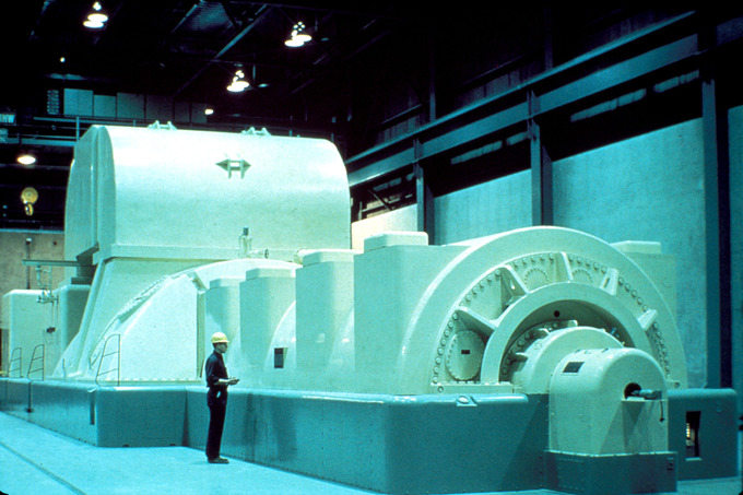
Steam Turbine Generator: A modern steam turbine generator.
Basic Setup
Consider the setup shown in. Charges in the wires of the loop experience the magnetic force because they are moving in a magnetic field. Charges in the vertical wires experience forces parallel to the wire, causing currents. However, those in the top and bottom segments feel a force perpendicular to the wire; this force does not cause a current. We can thus find the induced EMF by considering only the side wires. Motional EMF is given to be EMF=Bℓv, where the velocity v is perpendicular to the magnetic field B (see our Atom on “Motional EMF”). Here, the velocity is at an angle θ with B, so that its component perpendicular to B is vsinθ.
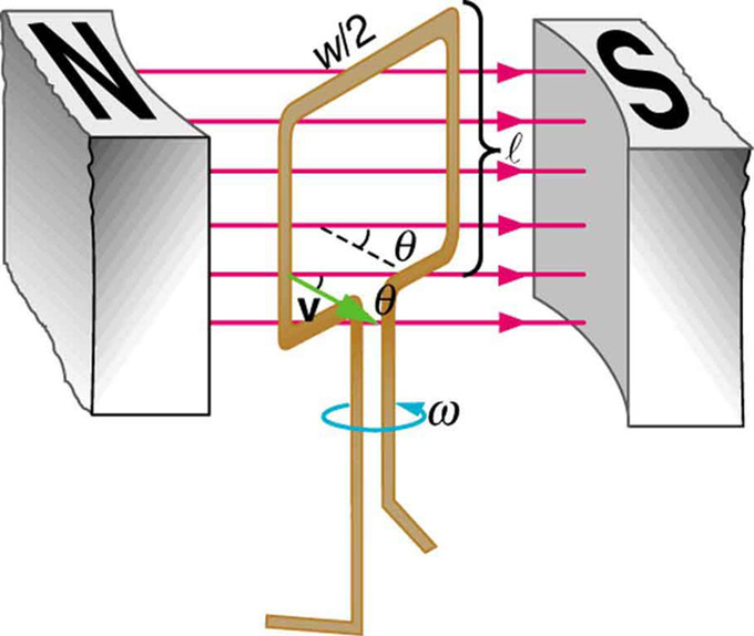
Diagram of an Electric Generator: A generator with a single rectangular coil rotated at constant angular velocity in a uniform magnetic field produces an emf that varies sinusoidally in time. Note the generator is similar to a motor, except the shaft is rotated to produce a current rather than the other way around.
Thus in this case the EMF induced on each side is EMF=Bℓvsinθ, and they are in the same direction. The total EMF [latex]\varepsilon[/latex] around the loop is then:
[latex]\varepsilon = 2 \text{Blv} \sin{\theta}[/latex].
This expression is valid, but it does not give EMF as a function of time. To find the time dependence of EMF, we assume the coil rotates at a constant angular velocity ω. The angle θ is related to angular velocity by θ=ωt, so that:
[latex]\varepsilon = 2 \text{Blv} \sin{\omega \text{t}}[/latex].
Now, linear velocity v is related to angular velocity by v=rω. Here r=w/2, so that v=(w/2)ω, and:
[latex]\varepsilon = 2 \text{Bl} \frac{\text{w}}{2} \omega \sin{\omega \text{t}} = (\text{lw})\text{B}\omega \sin{\omega \text{t}}[/latex].
Noting that the area of the loop is A=ℓw, and allowing for N loops, we find that:
[latex]\varepsilon = \text{NABw}~\sin{\omega \text{t}}[/latex] is the EMF induced in a generator coil of N turns and area A rotating at a constant angular velocity in a uniform magnetic field B.
Generators illustrated in this Atom look very much like the motors illustrated previously. This is not coincidental. In fact, a motor becomes a generator when its shaft rotates.
Electric Motors
An electric motor is a device that converts electrical energy into mechanical energy.
Learning Objectives
Explain how force is generated into electric motors
Key Takeaways
Key Points
- Most electric motors use the interaction of magnetic fields and current -carrying conductors to generate force.
- Current in a conductor consists of moving charges. Therefore, a current-carrying coil in a magnetic field will also feel the Lorentz force.
- In a motor, a current-carrying coil in a magnetic field experiences a force on both sides of the coil, which creates a twisting force (called a torque) that makes it turn.
Key Terms
- Lorentz force: The force exerted on a charged particle in an electromagnetic field.
- torque: A rotational or twisting effect of a force; (SI unit newton-meter or Nm; imperial unit foot-pound or ft-lb)
The basic principles of operation for a motor are the same as those for a generator, except that a motor converts electrical energy into mechanical energy (motion). (Read our atom on electric generators first. ) Most electric motors use the interaction of magnetic fields and current-carrying conductors to generate force. Electric motors are found in applications as diverse as industrial fans, blowers and pumps, machine tools, household appliances, power tools, and disk drives.
Lorentz Force
If you were to place a moving charged particle in a magnetic field, it would experience a force called the Lorentz force:
[latex]\text{F}=\text{q}\times \text{v}\times \text{B}[/latex]
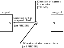
Right-Hand Rule: Right-hand rule showing the direction of the Lorentz force
where v is the speed of the moving charge, q is the charge, and B is the magnetic field. Current in a conductor consists of moving charges. Therefore, a current-carrying coil in a magnetic field will also feel the Lorentz force. For a straight current carrying wire that is not moving, the Lorentz force is:
[latex]\text{F}=\text{I}\times \text{L}\times \text{B}[/latex]
where F is the force (in newtons, N), I is the current in the wire (in amperes, A), L is the length of the wire that is in the magnetic field (in m), and B is the magnetic field strength (in teslas, T). The direction of the Lorentz force is perpendicular to both the direction of the flow of current and the magnetic field and can be found using the right-hand rule, shown in. Using your right hand, point your thumb in the direction of the current, and point your first finger in the direction of the magnetic field. Your third finger will now be pointing in the direction of the force.
Torque: The force on opposite sides of the coil will be in opposite directions because the charges are moving in opposite directions. This means the coil will rotate.
Mechanics of a Motor
Both motors and generators can be explained in terms of a coil that rotates in a magnetic field. In a generator the coil is attached to an external circuit that is then turned. This results in a changing flux, which induces an electromagnetic field. In a motor, a current-carrying coil in a magnetic field experiences a force on both sides of the coil, which creates a twisting force (called a torque) that makes it turn. Any coil carrying current can feel a force in a magnetic field. This force is the Lorentz force on the moving charges in the conductor. The force on opposite sides of the coil will be in opposite directions because the charges are moving in opposite directions. This means the coil will rotate.
Inductance
Inductance is the property of a device that tells how effectively it induces an emf in another device or on itself.
Learning Objectives
Describe properties of an inductor, distinguishing mutual inductance and self-inductance
Key Takeaways
Key Points
- Mutual inductance is the effect of two devices in inducing emfs in each other. A change in current ΔI1/Δt in one induces an emf emf2 in the seccond: EMF2= −M ΔI1/Δt, where M is defined to be the mutual inductance between the two devices.
- Self-inductance is the effect of the device inducing emf in itself.
- A device that exhibits significant self-inductance is called an inductor, and the EMF induced in it by a change in current through it is EMF = −L ΔI/Δt.
Key Terms
- Faraday’s law of induction: A basic law of electromagnetism that predicts how a magnetic field will interact with an electric circuit to produce an electromotive force (EMF).
- transformer: A static device that transfers electric energy from one circuit to another by magnetic coupling. Their main use is to transfer energy between different voltage levels, which allows choosing most appropriate voltage for power generation, transmission and distribution separately.
Induction is the process in which an emf is induced by changing magnetic flux. Transformers, for example, are designed to be particularly effective at inducing a desired voltage and current with very little loss of energy to other forms (see our Atom on “Transformers. “) Is there a useful physical quantity related to how “effective” a given device is? The answer is yes, and that physical quantity is called inductance.
Mutual Inductance
Mutual inductance is the effect of Faraday’s law of induction for one device upon another, such as the primary coil in transmitting energy to the secondary in a transformer. See, where simple coils induce emfs in one another.
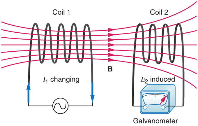
Mutual Inductance in Coils: These coils can induce emfs in one another like an inefficient transformer. Their mutual inductance M indicates the effectiveness of the coupling between them. Here a change in current in coil 1 is seen to induce an emf in coil 2. (Note that “E2 induced” represents the induced emf in coil 2. )
In the many cases where the geometry of the devices is fixed, flux is changed by varying current. We therefore concentrate on the rate of change of current, ΔI/Δt, as the cause of induction. A change in the current I1 in one device, coil 1, induces an EMF2 in the other. We express this in equation form as
[latex]\text{EMF}_2 = -\text{M} \frac{\Delta \text{I}_1}{\Delta \text{t}}[/latex],
where M is defined to be the mutual inductance between the two devices. The minus sign is an expression of Lenz’s law. The larger the mutual inductance M, the more effective the coupling.
Nature is symmetric here. If we change the current I2 in coil 2, we induce an emf1 in coil 1, which is given by
[latex]\text{EMF}_1 = -\text{M} \frac{\Delta \text{I}_2}{\Delta \text{t}}[/latex],
where M is the same as for the reverse process. Transformers run backward with the same effectiveness, or mutual inductance M.
Self-Inductance
Self-inductance, the effect of Faraday’s law of induction of a device on itself, also exists. When, for example, current through a coil is increased, the magnetic field and flux also increase, inducing a counter emf, as required by Lenz’s law. Conversely, if the current is decreased, an emf is induced that opposes the decrease. Most devices have a fixed geometry, and so the change in flux is due entirely to the change in current ΔI through the device. The induced emf is related to the physical geometry of the device and the rate of change of current. It is given by
[latex]\text{EMF} = -\text{L} \frac{\Delta \text{I}}{\Delta \text{t}}[/latex],
where L is the self-inductance of the device. A device that exhibits significant self-inductance is called an inductor. Again, the minus sign is an expression of Lenz’s law, indicating that emf opposes the change in current.
A Quantitative Interpretation of Motional EMF
A a motional EMF is an electromotive force (EMF) induced by motion relative to a magnetic field B.
Learning Objectives
Formulate two views that are applied to calculate the electromotive force
Key Takeaways
Key Points
- Motional and induced EMF are the same phenomenon, just observed in different reference frames. Equivalence of the two phenomena is what triggered Einstein to work on special relativity.
- The EMF produced due to the relative motion of the loop and magnet is given as [latex]\varepsilon_{\text{motion}} = \text{vB} \times \text{L}[/latex] (Eq. 1), where L is the length of the object moving at speed v relative to the magnet.
- The EMF can be calculated from two different points of view: 1) in terms of the magnetic force on moving electrons in a magnetic field, and 2) in terms of the rate of change in magnetic flux. Both yield the same result.
Key Terms
- special relativity: A theory that (neglecting the effects of gravity) reconciles the principle of relativity with the observation that the speed of light is constant in all frames of reference.
- magnetic field: A condition in the space around a magnet or electric current in which there is a detectable magnetic force, and where two magnetic poles are present.
- frame of reference: A coordinate system or set of axes within which to measure the position, orientation, and other properties of objects in it.
An electromotive force (EMF) induced by motion relative to a magnetic field B is called a motional EMF. You might have noticed that motional EMF is very similar to the induced EMF caused by a changing magnetic field. In this Atom we see that they are indeed the same phenomenon, shown in different frame of reference.
Motional EMF
In the case where a conductor loop is moving into magnet shown in (a), magnetic force on a moving charge in the loop is given by [latex]evB[/latex] (Lorentz force, e: electron charge).
Conductor Loop Moving Into a Magnet: (a) Motional EMF. The current loop is moving into a stationary magnet. The direction of the magnetic field is into the screen. (b) Induced EMF. Current loop is stationary, and the magnet is moving.
Due to the force, electrons will keep building up on one side (bottom end in the figure) until enough of an electric field opposing the motion of electrons is established across the rod, which is [latex]\text{eE}[/latex]. Equating the two forces, we get [latex]\text{E} = \text{vB}[/latex].
Therefore, the motional EMF over the length L of the side of the loop is given by [latex]\varepsilon_{\text{motion}} = \text{vB} \times \text{L}[/latex] (Eq. 1), where L is the length of the object moving at speed v relative to the magnet.
Induced EMF
Since the rate of change of the magnetic flux passing through the loop is [latex]\text{B}\frac{\text{dA}}{\text{dt}}[/latex](A: area of the loop that magnetic field pass through), the induced EMF [latex]\varepsilon_{\text{induced}} = \text{BLv}[/latex] (Eq. 2).
Equivalence of the Motional and Induced EMF
From Eq. 1 and Eq. 2 we can confirm that motional and induced EMF yield the same result. In fact, the equivalence of the two phenomena is what triggered Albert Einstein to examine special relativity. In his seminal paper on special relativity published in 1905, Einstein begins by mentioning the equivalence of the two phenomena:
“…… for example, the reciprocal electrodynamic action of a magnet and a conductor. The observable phenomenon here depends only on the relative motion of the conductor and the magnet, whereas the customary view draws a sharp distinction between the two cases in which either the one or the other of these bodies is in motion. For if the magnet is in motion and the conductor at rest, there arises in the neighbourhood of the magnet an electric field with a certain definite energy, producing a current at the places where parts of the conductor are situated. But if the magnet is stationary and the conductor in motion, no electric field arises in the neighbourhood of the magnet. In the conductor, however, we find an electromotive force, to which in itself there is no corresponding energy, but which gives rise—assuming equality of relative motion in the two cases discussed—to electric currents of the same path and intensity as those produced by the electric forces in the former case. “
Mechanical Work and Electrical Energy
Mechanical work done by an external force to produce motional EMF is converted to heat energy; energy is conserved in the process.
Learning Objectives
Apply the law of conservation of energy to describe the production motional electromotive force with mechanical work
Key Takeaways
Key Points
- Motional EMF produced by a moving conductor in a uniform field is given as follows [latex]\varepsilon = \text{Blv}[/latex].
- To keep the rod moving at a constant speed v, we have to apply an external force Fext constantly on the rod along its motion.
- Lenz’ law guarantees that the motion of the rod is opposed, and therefore the law of energy conservation is not violated.
Key Terms
- motional EMF: An EMF (electromotive force) induced by motion relative to a magnetic field.
- Faraday’s law of induction: A basic law of electromagnetism that predicts how a magnetic field will interact with an electric circuit to produce an electromotive force (EMF).
We learned about motional EMF previously (see our Atom on “Motional EMF”). For the simple setup shown below, motional EMF [latex](\varepsilon)[/latex] produced by a moving conductor (in a uniform field) is given as follows:
[latex]\varepsilon = \text{Blv}[/latex]
where B is the magnetic field, l is the length of the conducting rod, and v is the (constant) speed of its motion. (B, l, and v are all perpendicular to each other as shown in the image below.)
Motional EMF: (a) A motional emf=Bℓv is induced between the rails when this rod moves to the right in the uniform magnetic field. The magnetic field B is into the page, perpendicular to the moving rod and rails and, hence, to the area enclosed by them. (b) Lenz’s law gives the directions of the induced field and current, and the polarity of the induced emf. Since the flux is increasing, the induced field is in the opposite direction, or out of the page. Right hand rule gives the current direction shown, and the polarity of the rod will drive such a current.
Conservation of Energy
In this atom, we will consider the system from the energy perspective. As the rod moves and carries current i, it will feel the Lorentz force
[latex]\text{F}_\text{L} = \text{iBL}[/latex].
To keep the rod moving at a constant speed v, we must constantly apply an external force Fext(equal to magnitude of FL and opposite in its direction) to the rod along its motion. Since the rod is moving at v, the power P delivered by the external force would be:
[latex]\text{P} = \text{F}_{\text{ext}} \text{v} = (\text{iBL})\times \text{v} = \text{i} \varepsilon[/latex].
In the final step, we used the first equation we talked about. Note that this is exactly the power dissipated in the loop (= current [latex]\times[/latex] voltage). Therefore, we conclude that the mechanical work done by an external force to keep the rod moving at a constant speed is converted to heat energy in the loop. More generally, mechanical work done by an external force to produce motional EMF is converted to heat energy. Energy is conserved in the process.
Lenz’ Law
We learned in the Atom “Faraday’s Law of Induction and Lenz’ Law” that Lenz’ law is a manifestation of the conservation of energy. As we see in the example in this Atom, Lenz’ law guarantees that the motion of the rod is opposed because of nature’s tendency to oppose a change in magnetic field. If the induced EMF were in the same direction as the change in flux, there would be a positive feedback causing the rod to fly away from the slightest perturbation.
Energy in a Magnetic Field
Magnetic field stores energy. The energy density is given as [latex]\text{u} = \frac{\mathbf{\text{B}}\cdot\mathbf{\text{B}}}{2\mu}[/latex].
Learning Objectives
Express the energy density of a magnetic field in a form of equation
Key Takeaways
Key Points
- Energy is needed to generate a magnetic field both to work against the electric field that a changing magnetic field creates and to change the magnetization of any material within the magnetic field.
- For linear, non-dispersive, materials (such that B = μH where μ, called the permeability, is frequency-independent), the energy density is: [latex]\text{u} = \frac{\mathbf{\text{B}}\cdot\mathbf{\text{B}}}{2\mu} = \frac{\mu\mathbf{\text{H}}\cdot\mathbf{\text{H}}}{2}[/latex].
- The energy stored by an inductor is [latex]\text{E}_{\text{stored}} = \frac{1}{2}\text{LI}^2[/latex].
Key Terms
- permeability: A quantitative measure of the degree of magnetization of a material in the presence of an applied magnetic field (measured in newtons per ampere squared in SI units).
- inductor: A passive device that introduces inductance into an electrical circuit.
- ferromagnet: Materials that show a permanent magnetic property.
Energy is needed to generate a magnetic field both to work against the electric field that a changing magnetic field creates and to change the magnetization of any material within the magnetic field. For non-dispersive materials this same energy is released when the magnetic field is destroyed. Therefore, this energy can be modeled as being “stored” in the magnetic field.

Magnetic Field Created By A Solenoid: Magnetic field created by a solenoid (cross-sectional view) described using field lines. Energy is “stored” in the magnetic field.
Energy Stored in a Magnetic Field
For linear, non-dispersive, materials (such that B = μH where μ, called the permeability, is frequency-independent), the energy density is:
[latex]\text{u} = \frac{\mathbf{\text{B}}\cdot\mathbf{\text{B}}}{2\mu} = \frac{\mu\mathbf{\text{H}}\cdot\mathbf{\text{H}}}{2}[/latex].
Energy density is the amount of energy stored in a given system or region of space per unit volume. If there are no magnetic materials around, μ can be replaced by μ0. The above equation cannot be used for nonlinear materials, though; a more general expression (given below) must be used.
In general, the incremental amount of work per unit volume δW needed to cause a small change of magnetic field δB is:
[latex]\delta \text{W} = \mathbf{\text{H}}\cdot\delta\mathbf{\text{B}}[/latex].
Once the relationship between H and B is known this equation is used to determine the work needed to reach a given magnetic state. For hysteretic materials such as ferromagnets and superconductors, the work needed also depends on how the magnetic field is created. For linear non-dispersive materials, though, the general equation leads directly to the simpler energy density equation given above.
Energy Stored in the Field of a Solenoid
The energy stored by an inductor is equal to the amount of work required to establish the current through the inductor, and therefore the magnetic field. This is given by:
[latex]\text{E}_{\text{stored}} = \frac{1}{2}\text{LI}^2[/latex].
Proof: Power that should be supplied to an inductor with inductance L to run current I through it it given as
[latex]\text{P} = \text{VI} = \text{L}\frac{\text{dI}}{\text{dt}} \times \text{I}[/latex].
Therefore
[latex]\text{E}_{\text{stored}} = \int_0^\text{T} \text{P}(\text{t}) \text{dt} = \int_0 ^\text{I} \text{LI}' \text{dI}' = \frac{1}{2} \text{LI}^2[/latex].
Transformers
Transformers transform voltages from one value to another; its function is governed by the transformer equation.
Learning Objectives
Apply the transformer equation to compare the secondary and primary voltages
Key Takeaways
Key Points
- Transformers are often used at several points in the power distribution systems and also in many household power adapters.
- Transformer equation states that the ratio of the secondary to primary voltages in a transformer equals the ratio of the number of loops in their coils: [latex]\frac{\text{V}_\text{s}}{\text{V}_\text{p}} = \frac{\text{N}_\text{s}}{\text{N}_\text{p}}[/latex].
- Assuming, as we have, that resistance is negligible, the electrical power output of a transformer equals its input. This leads us to another useful eqaution: [latex]\frac{\text{I}_\text{s}}{\text{I}_\text{p}} = \frac{\text{N}_\text{p}}{\text{N}_\text{s}}[/latex]. If voltage increases, current decreases. Conversely, if voltage decreases, current increases.
Key Terms
- magnetic flux: A measure of the strength of a magnetic field in a given area.
- Faraday’s law of induction: A basic law of electromagnetism that predicts how a magnetic field will interact with an electric circuit to produce an electromotive force (EMF).
Transformers change voltages from one value to another. For example, devices such as cell phones, laptops, video games, power tools and small appliances have a transformer (built into their plug-in unit) that changes 120 V into the proper voltage for the device. Transformers are also used at several points in power distribution systems, as shown in. Power is sent long distances at high voltages, as less current is required for a given amount of power (this means less line loss). Because high voltages pose greater hazards, transformers are employed to produce lower voltage at the user’s location.
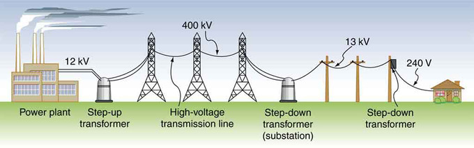
Transformer Setup: Transformers change voltages at several points in a power distribution system. Electric power is usually generated at greater than 10 kV, and transmitted long distances at voltages over 200 kV—sometimes as great as 700 kV—to limit energy losses. Local power distribution to neighborhoods or industries goes through a substation and is sent short distances at voltages ranging from 5 to 13 kV. This is reduced to 120, 240, or 480 V for safety at the individual user site.
The type of transformer considered here is based on Faraday’s law of induction, and is very similar in construction to the apparatus Faraday used to demonstrate that magnetic fields can create currents (illustrated in ). The two coils are called the primary and secondary coils. In normal use, the input voltage is placed on the primary, and the secondary produces the transformed output voltage. Not only does the iron core trap the magnetic field created by the primary coil, its magnetization increases the field strength. Since the input voltage is AC, a time-varying magnetic flux is sent to the secondary, inducing its AC output voltage.
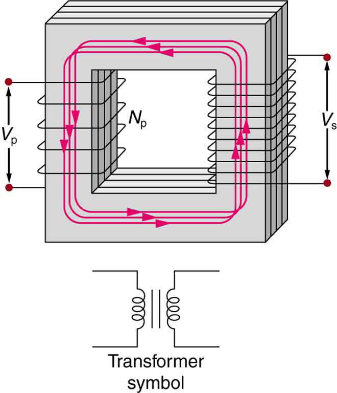
Simple Transformer: A typical construction of a simple transformer has two coils wound on a ferromagnetic core that is laminated to minimize eddy currents. The magnetic field created by the primary is mostly confined to and increased by the core, which transmits it to the secondary coil. Any change in current in the primary induces a current in the secondary.The figure shows a simple transformer with two coils wound on either sides of a laminated ferromagnetic core. The set of coil on left side of the core is marked as the primary and there number is given as N p. The voltage across the primary is given by V p. The set of coil on right side of the core is marked as the secondary and there number is represented as N s. The voltage across the secondary is given by V s. A symbol of the transformer is also shown below the diagram. It consists of two inductor coils separated by two equal parallel lines representing the core.
Transformer Equation
For the simple transformer shown in, the output voltage Vs depends almost entirely on the input voltage Vp and the ratio of the number of loops in the primary and secondary coils. Faraday’s law of induction for the secondary coil gives its induced output voltage Vs as:
[latex]\text{V}_\text{s} = -\text{N}_\text{s} \frac{\Delta \Phi}{\Delta \text{t}}[/latex],
where Ns is the number of loops in the secondary coil and Δ/Δt is the rate of change of magnetic flux. Note that the output voltage equals the induced EMF (Vs=EMFs), provided coil resistance is small. The cross-sectional area of the coils is the same on either side, as is the magnetic field strength, so /Δt is the same on either side. The input primary voltage Vp is also related to changing flux by:
[latex]\text{V}_\text{p} = -\text{N}_\text{p} \frac{\Delta \Phi}{\Delta \text{t}}[/latex].
Taking the ratio of these last two equations yields a useful relationship:
[latex]\frac{\text{V}_\text{s}}{\text{V}_\text{p}} = \frac{\text{N}_\text{s}}{\text{N}_\text{p}}[/latex].
This is known as the transformer equation, which simply states that the ratio of the secondary to primary voltages in a transformer equals the ratio of the number of loops in their coils. The output voltage of a transformer can be less than, greater than or equal to the input voltage, depending on the ratio of the number of loops in their coils. Some transformers even provide a variable output by allowing connection to be made at different points on the secondary coil. A step-up transformer is one that increases voltage, whereas a step-down transformer decreases voltage.
Assuming, as we have, that resistance is negligible, the electrical power output of a transformer equals its input. Equating the power input and output,
[latex]\text{P}_\text{p} = \text{I}_\text{p} \text{V}_\text{p} = \text{I}_\text{s} \text{V}_\text{s} = \text{P}_\text{s}[/latex].
Combining this results with the transformer equation, we find:
[latex]\frac{\text{I}_\text{s}}{\text{I}_\text{p}} = \frac{\text{N}_\text{p}}{\text{N}_\text{s}}[/latex].
So if voltage increases, current decreases. Conversely, if voltage decreases, current increases.
